+86 134 0021 8776
+86 134 0021 8776
Jul. 28, 2023
1, when making PCB design, in order to meet the total length of all signal lines in a group to meet a tolerance range, usually use the snake line to wrap the total length of the short signal line to the longest signal line in the group tolerance range, this process of winding the snake line around the long signal line is our commonly known as PCB signal iso-length processing. The goal of equal length is to meet the timing matching requirements of the same group of signals
2, the equal length range should strictly comply with the requirements of different interfaces or signals, the specific can refer to the module specification content. If in doubt, promptly confirm with the customer.
3. Before processing iso-length, the signal line with the longest length in the same group should be found, and the first step is to optimize the length of the longest signal.
4.After the isometric processing, the whole signal line path should be checked to check whether it avoids interference sources and check whether it is qualified.
5.isometric processing, preferably 4W spacing, such as space limited, can be adjusted to 3W; Isometric height control in 40-150mil is appropriate, can not be too high; The Angle length is not less than 1.5 times of the line width, and is generally controlled at 6-10mil size, such as the line width is 4mil, the Angle size is controlled at 6mil, and the Angle cannot be too small, as shown in Figure 1.
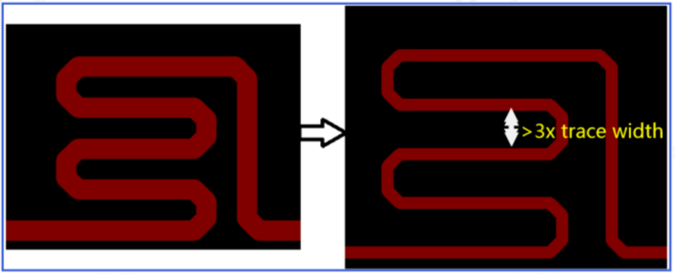
Figure 1 Serpentine routing requirements
6, the equal length should be processed in the horizontal or vertical direction as far as possible, avoid processing on the diagonal line; The processing can not be too scattered, should be concentrated as far as possible to ensure its beauty, in principle, after processing a signal, the second repair line next to it, and then the second length processing, in order to ensure the utilization of space and the overall design beauty. Within the same design, the height of equal length should be controlled almost the same, not too much difference, as shown in Figure 2.
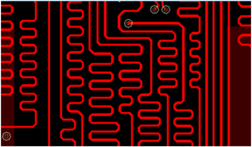
Figure 2 PCB serpentine isometric
7, After processing the length, should check its reference layer, do not allow its cross-segmentation. Important signals such as the clock signal on the PCB (generally ending in clock ) should also be avoided in the case of cross-segmentation, which will lead to signal impedance mutations after cross-segmentation.
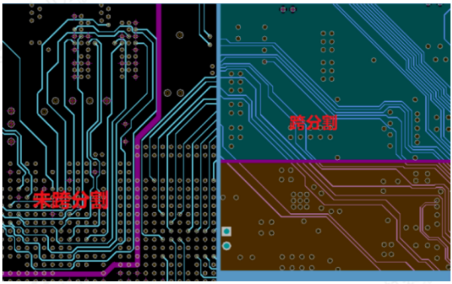
Figure 3 PCB routing segmentation
8.When the reference plane of the cable has cross-power layers, it is recommended to add ground capacitors to the two power layers respectively to provide a complete return path, as shown in Figure 4.
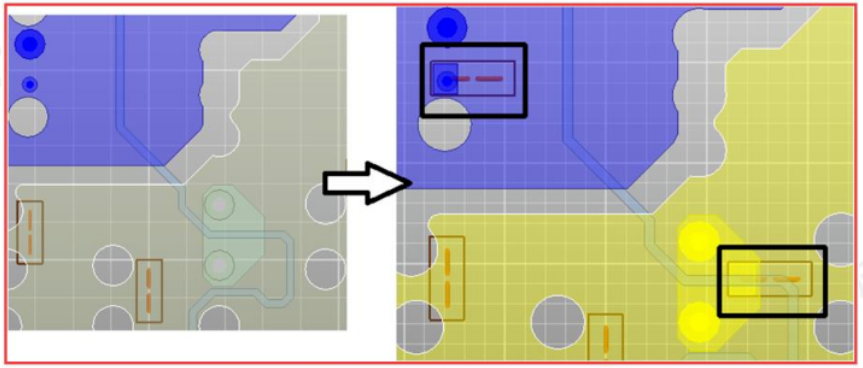
Figure 4 Wire crossing segmentation processing
9, the differential signal internal isometric position should be equiometric near the position generated by uncoupling, internal isometric height and width refer to the requirements shown in Figure 5 below.
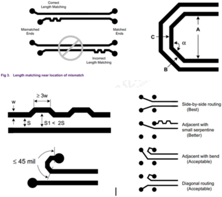
Figure 5 isometric requirements of difference lines
Previous: The difference between Flash and EEPROM
Next: The names of the layers of the Gerber file and the layers of the original PCB
Hot Products
Navigation
+86 134 0021 8776
Floor 9, Aupu building, No. 395 XinShi North Road, Shijiazhuang Hebei, China
Request a Quote
